.jpg.cf434708dc9183415367ced239248121.jpg)
straylight
-
Posts
255 -
Joined
-
Last visited
-
Days Won
6
1 Follower

Recent Profile Visitors
26,092 profile views


straylight's Achievements
")

-
.thumb.jpg.bd01cad9371554033557e35b9a182fea.jpg)
General Discussion - CarverFest 2026
straylight replied to sea's topic in CarverFest's Carverfest 2026
@Kurt Your BC merch store is a noteworthy tribute to theCarversite, to the Carverfest phenomenon and to our audio 'friend-in-chief' Bob Carver himself! Thank you my friend for such a worthy effort to continue this deserving and important audio legacy.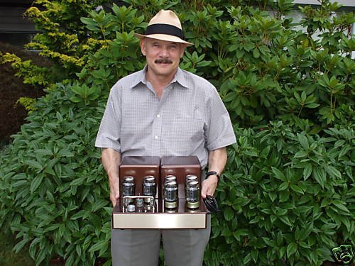
-
General Discussion - CarverFest 2026
straylight replied to sea's topic in CarverFest's Carverfest 2026
WOW! Not too shabby...the quality is so good you can see the 'mad professor' smile on Bob's face! Like the preamp this is REFERENCE LEVEL work Kurt! -
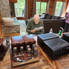
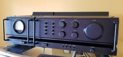
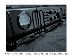
Bob Carver Vacuum Tube Reference Preamp Model-1 (aka Silver-1)
Images added to a gallery album owned by straylight in Member Albums
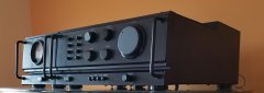
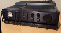
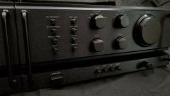
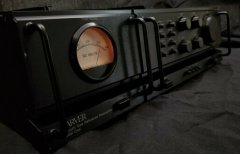
Photos of Bob's original Vacuum Tube Reference Preamp Model-1 also known by some members as the "Silver-1 Preamp" that Bob used on his test bench in the 1980's. A few additional PICS of Bob signing the preamp and other amps at Carverfest in September of 2024. -
-
General Discussion - CarverFest 2026
straylight replied to sea's topic in CarverFest's Carverfest 2026
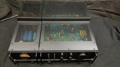
Kurt, Really appreciate the work you've done for the new CF logo and having Bob in the frame makes it that much better. Looking forward to the final design. In addition to adding Bob's image how about adding a couple of Mr. Carver's major contributions to the audio world like... The Carver Ref Vacuum Tube amp (what James S. used to call the Silver-1 preamp) that Bob had on his test bench in the 1980s and the Siver-7 Tube amps too that he developed at the same time! Both are important historically and are pinnacles of his audio design work over the years. We all know how much he loves the sound of tubes. I have some good pics of Bob's Ref preamp that I can send you and there should be ample pics of the Silver-7 Tube amps all over the internet! You might also consider putting the larger logo on the back of shirt with a very simple CF logo on the front. Might be more acceptable to all that way. Two versions of the shirt might also also work well to satisfy those interested in purchasing one or the other style. The AI tools of today are a double edged sword in many ways but seeing how you are using them here to our benefit gives me inspiration for the future! -
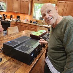
Reached out to Peggy via text this morning on the same text thread we had started last year about Bob possibly staying at our cabin in 2023...she responded quickly saying they are indeed coming. WOW! This is indeed thrilling news for the next Carverfest. I also asked Peggy if Bob would be able to sign the Vacuum Tube Reference preamp way back from his CARVER days... When she asked if I would bring a marker I said "I'll bring the marker if you bring the Bob!" Can't wait to get this puppy signed.

-
Hi Ed, Kirk and Russ and spouses planning to attend (cabin 11). Called Chelsea for reservation dates but she was out of the office today. Will update when I hear back from her.
-
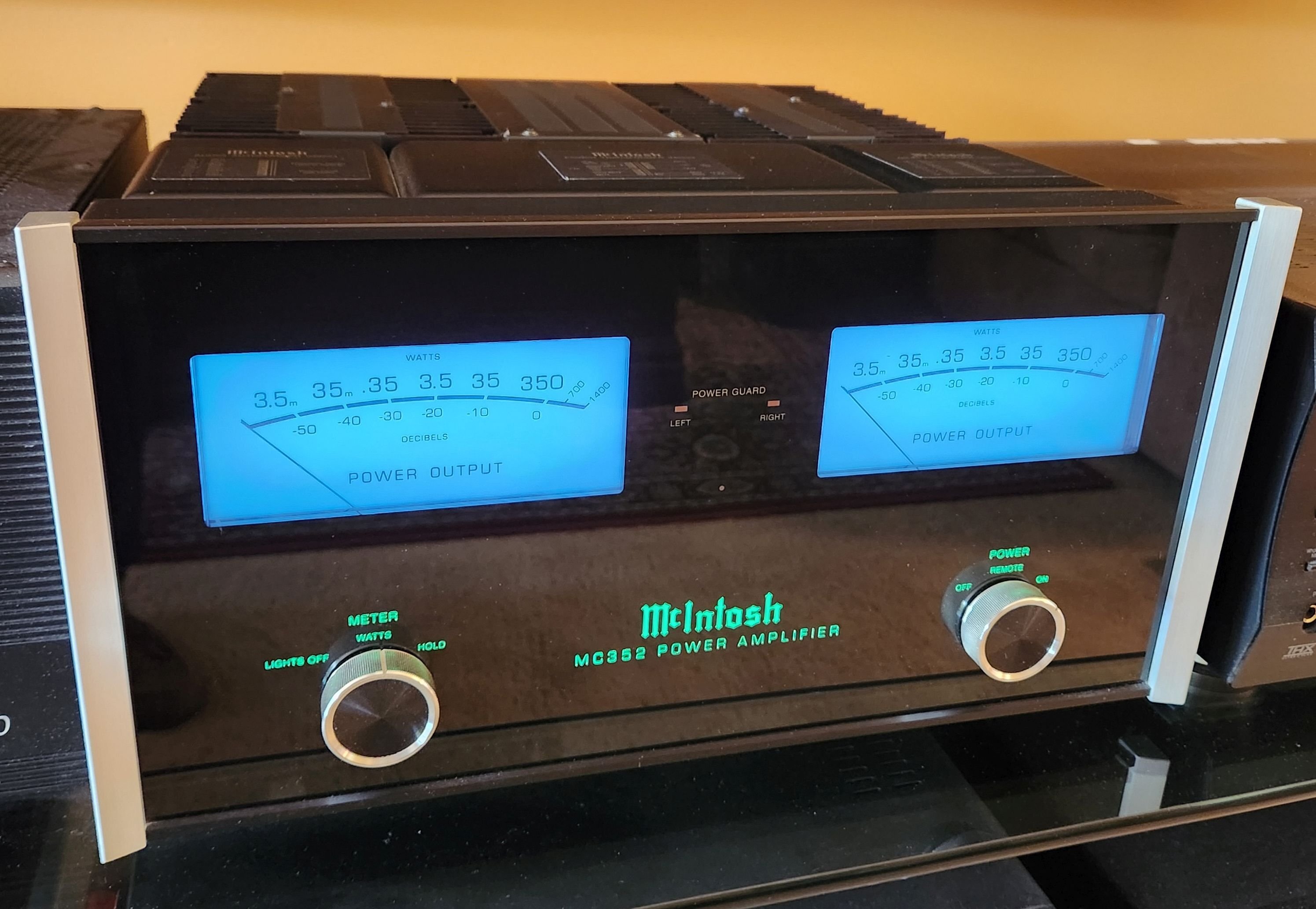
All very good questions. The McIntosh amp you see below is a MC352 stereo amp designed by Gordon Gow (one of the founders of the McIntosh company ) that has both solid state transistor outputs and also output transformers (look for them on the right and left in photo right behind the faceplate). They are bifilar wound transformers. Amp has 4 separate amplifier circuits in it. Each amp section handles 1/2 of the musical wave (top vs. bottom) and the trannies are some of the finest sounding transformers in production today. In fact there are lots of McIntosh amps and perhaps other brands that have the same configuration, so yes it has been done. Its an incredible sounding amp and although it does not sound like a tube amp it is very smooth and clean when you listen to it even at ear blistering levels. Listening fatigue is very low even after hours of listening. I believe this is attributed to the quality of the trannies and their bifilar nature. It is the most expensive type of transformer to manufacture. Regarding the 'cone movement' and 'Carver Challenge' Bob told me that before he even entered into the challenge he had already duplicated the null matching in his own lab. But he was also using an oscilloscope and perhaps other tools to monitor the difference signal between his amp and the challenge amp. So he probably achieved the 'least' difference in speaker movement (or oscilloscope trace difference) because getting 100% null is probably near impossible. The trick is to get it just below the level of human perception of the difference. So this does not not necessarily mean the amps had the same damping factor at all. In fact it would be highly unlikely that they had exactly the same damping factor but the null process may have assisted in reducing the overall difference between them somewhat. Remember the 'cone control' for the null test is less about cone control and more about nulling the difference signal between amps....you are using cone movement (or oscilloscope trace) to detect the amount of difference...and you might just have to ask Bob for a definitive answer on that point. It would be a very interesting result if the entire null process made the damping factors equal...so I'm not ruling that out because it would be very interesting to consider but I suspect there is much more at play here between amps than just damping factor (like significant distortion products, transient response characteristics and phase related anomalies in the two amp signals). Regarding your last question tube amps have been designed WITHOUT output transformers but the tubes are a special type and only work in circuit designed to accept them. I have been told that these amps have a 'live' and 'zippy' sound, not at all like the smoothness of tubes. But they can operate completely devoid of matching output transformers. A good example is the Futterman OTL Amp: https://jacmusic.com/techcorner/ARTICLES/English/Harvey-Rosenberg/futterman.htm BTW - I don't think you can build a tube amp with power transistors - its a mismatch from the start since circuit-wise they each have very different operational requirements. However you CAN build transistor amps with MOSFET transistors which sound more like tubes than transistors because their distortion and clipping characteristics sound more tube-like.

-
Look at 'In practice' section of link above.
-
https://en.wikipedia.org/wiki/Damping_factor
-
Grace Potter and Joe Satriani 'kill' 'Cortez the Killer'...
-
DF related changes in bass EQ response reported by Atkinson were measureable as several db over a broad range of bass frequencies (especially at or near the system resonant frequency)...therefore audible...not just opinion or myth.
-
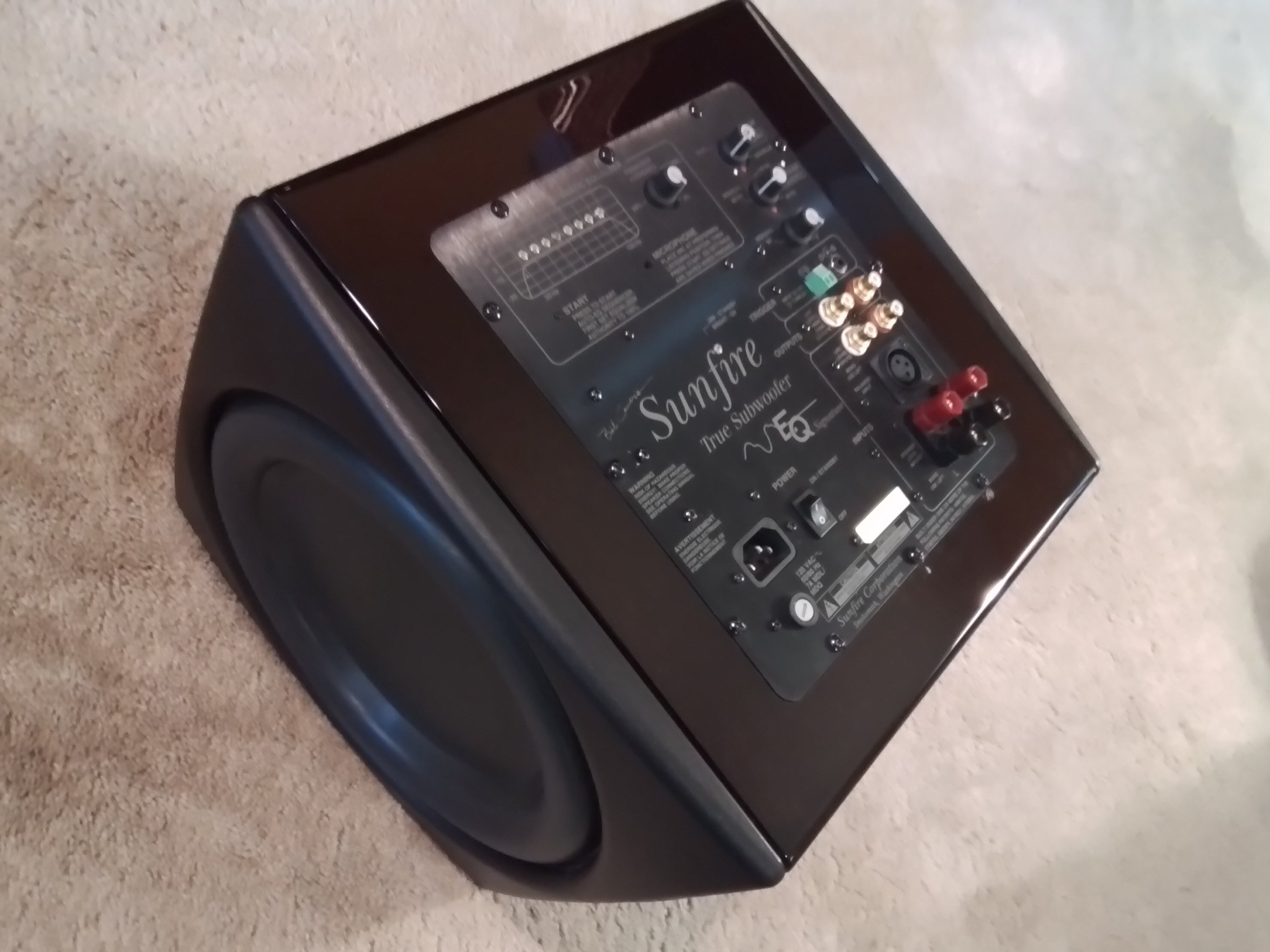
This has also been my experience with dual voice coil woofers and somehow using those two channels seems to make it a bit more dynamic than when driving with one channel only. I have owned Bob's Sunfire True Subwoofer EQ...with its built in EQ, passive radiator and 2700 watt amp for many years now...its a killer unit. There is nothing else that can rumble the walls for movie soundtracks or stereo listening. Just got it back after recent repair at Deltronics.

-
Sorry for not replying sooner but I have been away. Judging by the links you have provided and your well referenced reply we can probably both agree that the topic of amplifier-loudspeaker interaction is very complicated and perhaps one of the least understood areas of audio. So its a great topic to debate on the forum. After reviewing your first reference which takes a position to debunk the connection between DF and controlling cone movement I may have a tendency to agree with you on that particular point. However that does not mean DF is unimportant to the perceived sound of a loudspeaker or subwoofer. The following is taken from the Wikipedia link you provided on DAMPING FACTOR: "John Atkinson and Stereophile have recognized the importance of amplifier damping factor, and have made the use of the simulated loudspeaker load a routine part of their measurements of amplifiers. It is clear from the various amplifier frequency response curves that low damping factor values result in significant changes in the frequency response of the amplifier in a number of frequency bands. This will result in broad levels of sound coloration that are highly likely to be audible. "the amplifier with the low damping factor is acting more like a graphic equalizer than is the amplifier with the moderate damping factor." "Some amplifier designers, such as Nelson Pass, (of Threshold) claim that loudspeakers can sound better with lower electrical damping, although this may be attributed to listener preference rather than technical merit." The fact that both Atkinson and Pass take up opposite positions on the DF issue seems to indicate that despite their differences they at least each believe it is very important to the sound produced by the amp-speaker combination. I too have heard the bass related difference they talk about between low damping factor and high damping factor amps. Tube and transistor amps have widely different DF characteristics (yes, among many other differing characteristics) . Although this may have nothing to do with the effectiveness of an amplifier to tightly control cone movement the DF related EQ coloration is nonetheless still present in the amplified signal and therefore audible to the listener. One might even go as far as to say that perhaps the 'graphic equalizer effects' or 'tone alteration' produced by low damping amps might tend to make the listener hear or perceive a less tight bass response than a high damping factor amp due to addition bass coloration peaks that are artificial and an artifact added to the original bass output in the low DF amp. Unless you have something else to add I'll respectfully stay with my original statement to Kurt ..." However, the damping factor of the amplifier may play a bigger role in the SW sound than the number of channels you drive it with."
-
One possible advantage of DVC subwoofers is the ability to drive the subwoofer with more power and spread the drive wattage across two voice coils instead of just one. Will this make a difference in bass dynamics or perceived quality of sound output? That would likely depend on your particular subwoofer design. Its easy to find out though...just drive it with one channel (L) of a stereo amp and listen....then change over to driving it with two channels (L+R with mono input) to hear the difference and let us know what you hear. Some SW models might perform better with two channels driving them but others may not. The back EMF of two channels may do a better job of controlling the SW driver movement. However the damping factor of the amplifier may play a bigger role in the SW sound than the number of channels you drive it with.
-
Hi Ed, Russ and Kirk (and wives) plan to stay in cabin 11 and really look forward to seeing everyone again for CF 2023. We all had a blast last year and it was really great to meet everyone. We will most likely stay for most if not all of the scheduled dates but will let you know if that changes.