

markfugate
-
Posts
19 -
Joined
-
Last visited
-
Days Won
1
markfugate's Achievements
")
1/4W Resistor (3/21)
9
Reputation
-
B-Man, First, I have no test equipment. My evaluations are purely subjective. That is, 'does it sound better to me?' after living with a configuration for a multitude of listening sessions. I was discussing subjective evaluations with a friend that is an electrical engineer earlier today and my friend Randy told me "I [Randy] pursued electrical engineering because of my [Randy] love of audio, and that proves there is more that we don't know than what we do know with regards to measuring electrical systems". My asserted capacitance values are based upon calculations which can be found in "Harry E. Green, A Simplified Derivation of the Capacitance of a Two-Wire Transmission Line, IEEE Transactions on Microwave Theory and Techniques, Vol. 47, No. 3, March 1999, p. 365-366" and online calculators. A couple of such quick calculators can be found at the links below: http://www.ampbooks.com/home/amplifier-calculators/wire-capacitance/ http://www.cirris.com/learning-center/calculators/174-cable-capacitance-calculator I have used both and prefer the first one because it is the quickest and easiest. And, if someone believes that I am being less than 'scientific', so be it, it's my listening pleasure and fun that is my highest priority. My first two configurations had a high degree of hum and another suffered from noise. I addressed hum with distance separation and ordering of the conductors, and adding a single twist around my two inch cotton core. That caused all of the conductors to cross each other in a perpendicular manner a single time between the turntable and the preamp. The left and right hot wires were at the farthest distance from each other which gave them an 8 cm separation. The associated commons were in the middle and separated by 2cm from each other and their associated hot wires. The end result was an honest consistent 180 degree sonic image which also had greater depth than I had ever heard before without the sonic hologram. This also greatly enhanced the sonic hologram. I should also add that I also use cotton dielectric interconnects between my preamp and power amps. I use the M400t's in a passive bi-amp configuration. Just stereo here. Concerning noise, I was able to eliminate non-ambient, external EMI and RFI noise, and noticeably reduce ambient noise using an old trick I call a "Magic Brick". I can not take credit for the Magic Brick because I first read about this in an 'Absolute Sound' product review back around 1980 or so. However, I can claim some credit for my version of the Magic Brick (a picture of one will be inserted below). Don't laugh or guffaw until you try this and live with it for a period of time. My Magic Brick is nothing more than a cigar box packed full of ransom sized ferromagnetic objects, antenna ground wires of random lengths and twists, and pennies all wrapped in copper foil, and placed above power transformers and any large inductors. Except of course speakers. I also use numerous power cord ferrites on all power cords. I do not believe that any one of these tricks, other than the interconnects and my handcrafted speaker cables makes a huge difference. I believe that all of these things in conjunction with some tricks combined makes the improvements. That being said, don't expect that just adding power cord ferrites, or changing one set of interconnects will yield the results I have experienced. I often times think I have been lucky and have also wondered what sort of mileage other may get? Two Magic Bricks setting atop M400t's My choice of cotton as my dielectric/insulation is because I needed a substrate to keep all wires uniform. I chose not to use any other materials because I wanted to eliminate all dielectric absorption that was possible. That is why I do not use Teflon, polyolefin, TechFlex, or worst of all, PVC and stranded wires. The only foreign material is a wee tiny bit of Kester 60/40 solder in the smallest amount. The 30 AWG wire shows through the solder joint.
-
We're neighbors by DFW standards
-
If you're talking about my cable pic I actually call them FLATEs (Fart Loud And They Explode).
-
How about that Greenbay Dallas game? I'm a "Cheesehead" living in Colleyville.
-
Andrewjohn, Thanks for your comment. My design goal was to attempt to get as close to an air dielectric as possible and eliminate as many forms of dielectric absorption and potential capacitance as possible. Therefore, I am limiting myself to cotton which yields a 99% air dielectric. My very first experiment was wire in the air not surrounded by anything knowing that I would have high hum and noise. Surprisingly, I was able to reduce hum by shifting the wires around, and reduce noise using shields over the power supplies of the other components. I will make the final set of interconnects when my RCA connectors arrive. This final configuration will use cotton clothesline rope wrapped tightly with cotton twine to insulate the hot wires in the barrels of the connectors. I am also going to rework the core to make a slight upward curve to raise my preamp further above the turntable and power amplifiers.
-
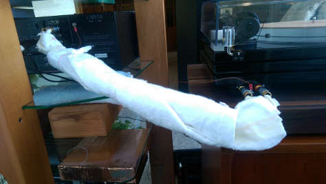
Weitrhino I told you they were ugly. However, in my defense, this huge honkin wad of cotton changed in many ways over a few days time until I settled on what is in the picture. I will redo these after I receive some RCA connectors that I have ordered and make them more palatable to the eyes. There are three layers of cotton: 1. A 5 cm (2") core made from cotton batting. 2. A flat layer of a heavy cotton fabric that looks like cheese cloth which I threaded the silver wire through to maintain a consistent parallel distance between the individual wires. The wires are separated by 2 cm and ordered as L+ L- R- R+. This was wrapped one turn around the core. 3. A final layer of cotton batting to hold it all together. Go ahead and laugh and poke fun, but it worked. This was my fifth configuration.
-
Zoom, I picked up the C1 just yesterday a few hours after the power supply in my C-4000 smoked. I attempted to plug my two M400t's into the switched preamp AC outlets. That was quite an act of 'Stupid'. Previously I had my 400's plugged into an isolation transformer leaving them powered up 24/7. Today they are back on the isolation transformer and I'm going to leave them there. I would truely appreciate some guidance with regards to fixing the C-4000. Also, I would love to be able to disable the time delay amplifier in it. I experimented with time delay for a few months and about all I was able to accomplish was mucking up the sound. I used the internal time delay amplifier for less than an hour then fed the time delay preamp outputs to a separate amplifier. I learned that I did not like the time delay. AS for pics, I will wait until I remake my cables. My setup looks quite ugly, but I believe that it sounds nice, and that's what counts. Maybe 'Beauty is in the ear of the Audiophile' is relevant here? The ugliness comes from trying to be as extreme about configuration as possible. It's not an easy trick to keep a turntable only inches from a preamp wile keeping cables as far separated as possible. And next to impossible to eliminate acoustic reflections without making the listening room like a place where the military conducts bomb testing.
-
Thanks PMAT. I'm here to learn and hope to find some like minded folks to discuss this stuff and learn from them.
-
Hi all I am also new to this site and have enjoyed reading. I was deep into Hi-Fi over thirty years ago until I returned home from work one evening finding all of my equipment except for my collection of vinyls stolen. I swore at that time I would carry my vinyls around and never play them until I was able to set up some respectable equipment. Well, short story made longer, I took a plunge and set up the following: Music Hall 9.1 turntable with the stock Goldring Eroica LX cartridge Carver C1 preamplifier Two Carver M400t amplifiers driving a pair of Klipsch RF-82 speakers in a Bi-Amp configuration. I handcrafted 30 AWG 99.9999% pure silver interconnects between all components except the speakers using only pure cotton as insulators/dielectrics. I calculated a total cable capacitance between the turntable and preamplifier of 2.4 pf - 2.7 pf. The turntable interconnects are 'loosely' a twisted pair with a two inch diameter core. This resulted in a single twist for the entire length. Initially, I had no twist on the turntable interconnects and experience both hum and noise. The single twist canceled all of the hum and noise. I used four runs of twisted plenum CAT5, one run for each speaker terminal from each of the M400t's to each connector on each speaker. This gives me an effective 15AWG between each amplifier terminal and each speaker connector.