Nahash5150
-
Posts
8,020 -
Joined
-
Last visited
-
Days Won
389
Content Type
Forums
Events
Articles
Downloads
Gallery
Store
Everything posted by Nahash5150
-
Miles Davis - SO WHAT
-
Billy Joel - Uptown Girl @1:27 Brilliant bridge. What a legend.
-
 Tests great too!
-
Gold RCA jacks for pre-amps
Nahash5150 replied to Nahash5150's topic in Nelion Audio's Vintage Audio Repair and Restore
C-16 (this was torture!)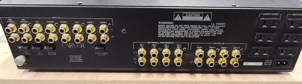
-
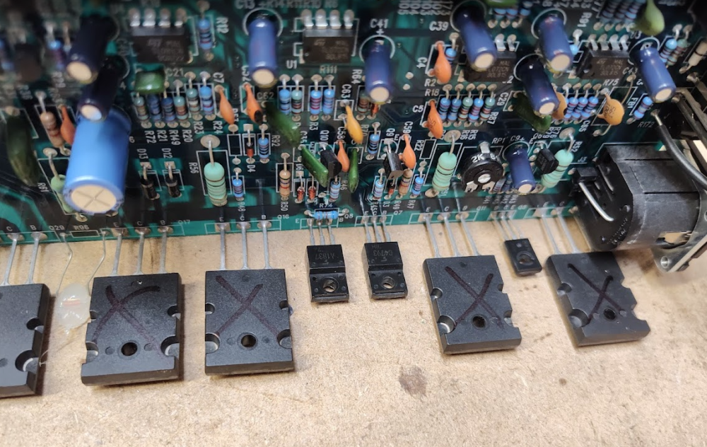
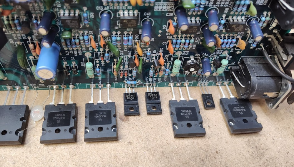
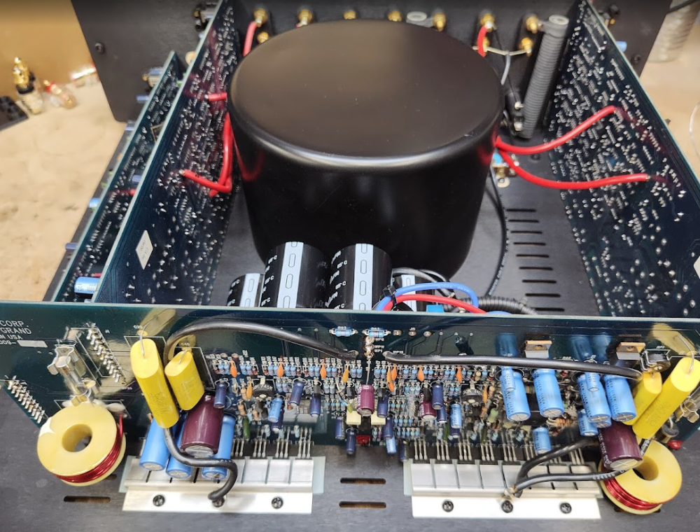
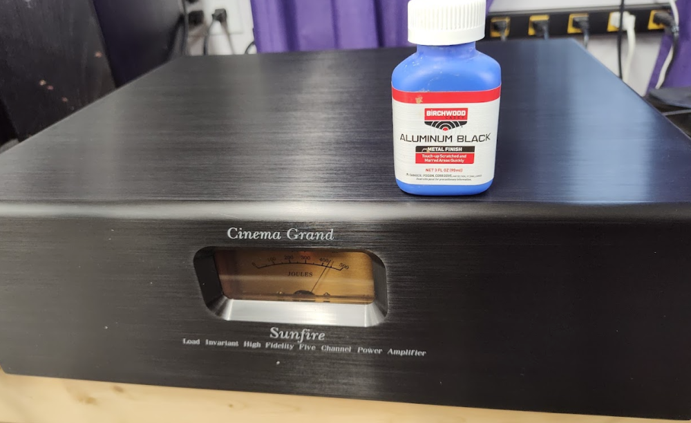
Bad bad bad! Thankfully, only a fuse and a pair if output transistors are bad. I replaced the whole stage though. All back together! New meter bulb and meter check, the cover is back on, and now a bit of faceplate cleanup Before: After:

-
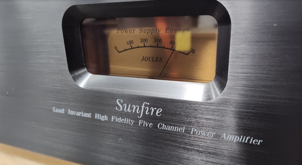
Not really typical. They fail as a result of a few things like a failed TDC, bad regulation (bad caps), cracked solder joints, abuse, etc. The problem is that Sunfires don't shut down from a fault - they just mute. So power stays active during a failure until it becomes a light show. The fuses rarely save the day...they only prevent complete meltdown (hopefully).
-
McIntosh 240 chassis replacement
Nahash5150 replied to Nahash5150's topic in Nelion Audio's Vintage Audio Repair and Restore
Yeah - 20 hours is at the low end of time. I will not make any money on this. I have bills like anyone else - it's not about making money, it's about being responsible with it. I have to be very careful what work I take. If a project gets too demanding of my attention, other clients suffer. And I certainly do not want a shop full of unfinished projects that are over a year or two old. I told myself I would not do that... Anyway, fxbill is a great salesman. Looks like I'm doing it. For team Carversite...here we go... -
McIntosh 240 chassis replacement
Nahash5150 replied to Nahash5150's topic in Nelion Audio's Vintage Audio Repair and Restore
Correction - FxBill worked on it and he says it works...so...that is a bonus! -
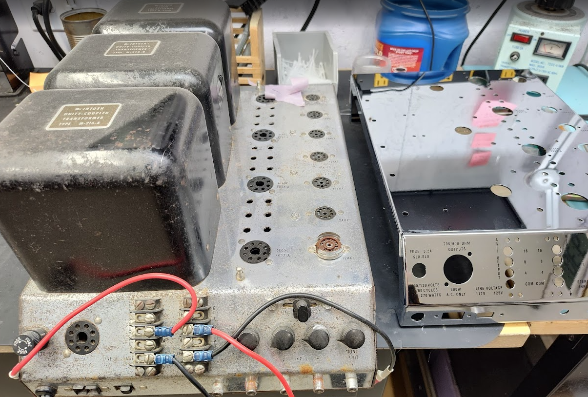
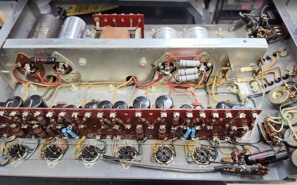
I may or may not do this...I'm having second thoughts. 'The guts just come out and go right into the new chassis...' Ha!!!!! It wouldn't be too bad if the transformers could just 'unplug' but they don't. Their wires travel everywhere...and that's real problem. There's no room for error - the wire lengths are precise. 3 transformers - each with 8 to 20 wires. All rivets have to be drilled out. All RCA jacks need to be replaced. The thing needs a severe cleaning and polishing. And the worst part - HUMAN HANDS. Previously worked on and it doesn't work. Worst problem ever. I'll need encouragement because I really want to say NO.

-
Tearing it down: And of course it has a blown channel...it's rare to work on a CG and it NOT have a blown channel.
-
I use these: https://www.mouser.com/ProductDetail/REAN/NYS367-0?qs=R5cXQUTKuHU8XkQYanQZXg%3D%3D The number after the dash selects the color. The above is black.
-
General Discussion - CarverFest 2026
Nahash5150 replied to sea's topic in CarverFest's Carverfest 2026
With a knife... -
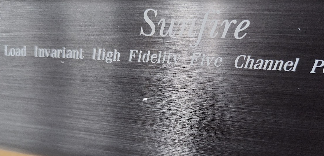
a) this is not a full range audio device, it's a sub and has a brick wall low pass filter at 200Hz b) likely required by UL/IEC for safety from static electric discharge on the processing side c) only when it needs to, to prevent catastrophe d) It's a half-wave circuit - it just look strange because it's illustrating a full-wave device.
- 1 reply
-
- 4
-

-
Today is the 50 year anniversary of the Wreck of the Edmund Fitzgerald. Something I learned just today after watching a documentary - this recording was not a first take, it was the first time the band had ever played it. They tried recording more sessions but none were as good as this one, so this is what we have today. The only take, first time ever played by these guys! btw - it is still unknown how the ship went down.
-
Repairs to my New M-1.0t
Nahash5150 replied to Vintageaudiorevival's topic in The Welcome Shop (Please read first)
Then we need to go to amplifier repair 101, especially after finding shorted pre-drivers. Check these resistors since you didn't mention them: R154, 156 43R FR VAS HR emitter R146, 144 10R signal coupling R168, 170 10R FR HR low current R172, 174 10R signal coupling R196, 198 22R, 27R CMR bias Deviations more than 10% are BAD PARTS. -
carver c1 preamp infrasonic filter
Nahash5150 replied to robertcdt's topic in The Welcome Shop (Please read first)
The new RC4136Ns at Mouser are drop in. However using a socket on these chips does not present the problem in the C1. Special care is needed when replacing the op amps in a C1. It's very easy to lift the pads or break traces. As for whether you need to change one or not depends on what the problem is. If you don't have the knowledge and the equipment to assess what's causing the issue then changing the op amp can be a reasonable next step, provided you have good workmanship, but of course there's no guarantee this will solve the problem. 'Popping' is normally caused by a difference in voltage from one circuit to the next. The op amp could have a slight DC offset, there could be a bad solder joint somewhere, the switch itself could be really noisy even after cleaning, etc. If you could see the frequency response of the filter this would make everything so much easier. Because if it's working correctly then a little bit of noise is not a big deal because it's not like you stand there and play with the switch while you're listening to music. The more often you use the switch then the cleaner it will become. They are slide contact switches so they clean themselves the more often they are used. Convenient! -
Repairs to my New M-1.0t
Nahash5150 replied to Vintageaudiorevival's topic in The Welcome Shop (Please read first)
Hello, That's definitely not normal, and not the kind of anomaly the 'thump fix' was designed to correct. One could swap the input board connectors between left and right to see if the problem is in the input section or in the amp stage. I have a suspicion it's the muting circuit in the input board. -
Welcome! It needs a restore. Those amps have a lot of problems due to age/use and it's best to stop using it until you get it restored, otherwise there could be smoke. The crackling is indicative of more trouble ahead. It needs more than a recap and I highly recommend Nelion Audio (us!) because we know what we're doing and we stand behind our work.
-
carver c1 preamp infrasonic filter
Nahash5150 replied to robertcdt's topic in The Welcome Shop (Please read first)
As others have said, that switch should be inaudible when activated or not. It rolls off frequencies lower than about 10Hz (these are so low we can't hear them, but the speakers can still respond to them) , which protects your speakers from 'rumble' generated from turn tables. However, if you use speakers which utilize sound ports for better bass response, it's a good idea to keep that filter active since vented cabinets tend to 'run away' from infrasonic signals which might be present in any media, and overextend the woofer, leading to damage. There are no less than 8 versions of the M-1.5(t) !!! -
Sunfire vaccuum tube preamp
Nahash5150 replied to Parmaniac's topic in The Welcome Shop (Please read first)
Hello! I just installed one for a VTCC last week. They are $600 installed. You'll need to also buy 6 tubes - 4x 6922's and 2x 12AX7's. No one who has ever used one of these has gone back to using an external. This phono board is AMAZING. Those are Telefunken Black Diamond 6922's and Eletro-Harmonix gold pin 12AX7's. The 12AX7's are for the subsonic filter, so they don't need to be uber expensive tubes there.
-
The bias should stay between 50mA and 150mA at idle after 10 minutes of warm up. If you've chosen your sweet spot, say 90mA (because that's mine), then it shouldn't change. If it does by more than a few mA, then it could indicate a problem, especially if it won't adjust properly or keeps falling out of your sweet spot. We aren't taking over the warranty. We are just willing to service these units and do our best to support them, unofficially, because right now, there is no official support. I'm sorry I don't know the exact origin of the trouble. I just know that it seems to be related to time, nothing else.
-
For those experiencing issues with the bias setting on the RAM285, the issue is likely with the burn-in effect of the circuit and transformer winding that powers the bias circuit. Many Bob Carver Corp amplifiers experience this trouble. Common complaints are: - The bias does not adjust high enough. - The bias does not adjust low enough. - The meter is not working. Unfortunately, there is no DIY fix for this. The RAM285 has extremely unfriendly serviceability. The PCB hides most components and is multilayered. Reworking the circuit board requires technical experience and proper tools. Moreover, the trouble has common causes but it may also be related to other less common troubles, so the amplifier should be fully tested to verify what the real trouble is. Please inquire with us to get your RAM285 serviced if it is experiencing any trouble.
-
I used Krud Kutter - The Must for Rust solution
-
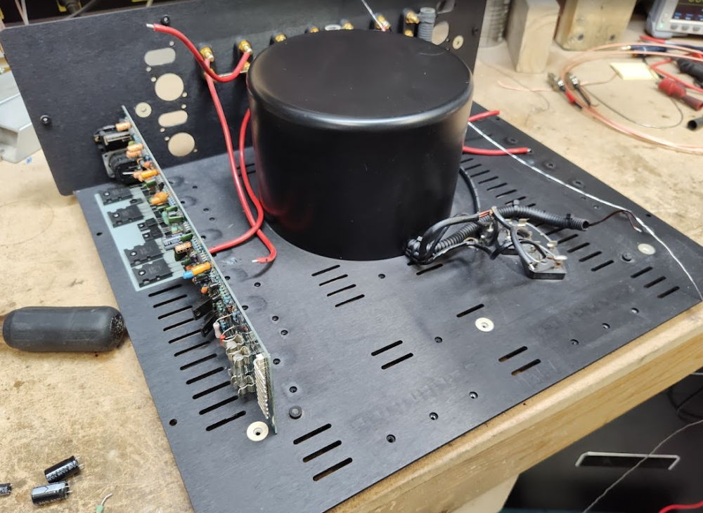
A received a Hafler DH-220 to fix along with an extensive upgrade kit. It came with a USB drive with docs and pics. A well put together project. The unit was in dire need of service. Old, crusty, and very dirty. Top of unit: Near power switch and primary fuse: Taken apart: I removed most of the screws and derusted them, then cleaned and derusted the chassis, heat sinks and other various parts. It was a load of work! But it cleaned up pretty good. All new amp driver boards that had to be stuffed by hand. Crazy! New speaker binding posts and RCA jacks as well. It looks so much better now though: Sorry - forgot to snap a picture of it all put together. But here's an internet one:


-
We can do that... C-4000 C-1