Ar9Jim 6,060 Posted October 9, 2023 Share Posted October 9, 2023 In this thread we will share the design philosophy and viewpoints of one of the worlds most famous and prolific audio designers. Bob Carver's point of view is based on his physics degree's from the University of Washington, followed by decades of experience and experimentation into what approaches sound the best and deliver the most enjoyable musical performance when driving loudspeakers. I'm humbled to have spent many weeks in Bob's lab and have asked many many questions about his philosophy and how it often differs widely from the mainstream. There is a lot to share. Enjoy! Jim Clark Director of Operations Bob Carver Company jim@bobcarvercorp.com 815-985-3557 5 Link to comment Share on other sites More sharing options...
Ar9Jim 6,060 Posted October 9, 2023 Author Share Posted October 9, 2023 (edited) Bob, I notice the tendency for amplifiers designs to brag about highly regulated 'stiff' power supplies, but you talk about designing power supplies to be bouncy and springy. This seems in conflict, how do you design a supply to act bouncy or springy? Bob Carver - That describes my philosophy pretty well. What I do, is start out with higher voltage power supply designs by over 200 volts in most cases. By using a smaller transformer the voltage will sag, rebound and bounce acting springy. You can design for higher current or higher voltage. It cost less to design for higher voltage and it sounds better. Nice wide voltage swings and lots of headroom is what I like. The current needs to be enough. Edited October 9, 2023 by Ar9Jim 3 Link to comment Share on other sites More sharing options...
Ar9Jim 6,060 Posted October 9, 2023 Author Share Posted October 9, 2023 Bob, The Phase Linear 700 was a game changer for amplifier power by a large margin. How did you do that? Bob Carver - Higher voltage devices were key. The transistors amplifiers at the time could provide lots of current, but not much voltage. I said to heck with that, I want voltage! As it turned out, General Motors had some transistors in their ignitions that could handle huge voltage in KVs but not much current, so I filled the back panel with as many of those transistors as it would hold, then the current was enough. It made 700 watts, way more than anything else and put me on the map. 1 2 Link to comment Share on other sites More sharing options...
Ar9Jim 6,060 Posted October 9, 2023 Author Share Posted October 9, 2023 (edited) Question about the 275 being so light. Q) Bob, audio designers often talk about highly regulated 'stiff' power supply designs for amplifiers, you on the other hand, talk about designing supplies to be "bouncy or springy" in concept. Where does this ability to bounce enter the design? How do you do that? You are using lighter weight transformers as well. Help me understand. The design has been criticized on-line in resistive load bench test, but we sell them compared head to head in customers homes and we always win. A) That's a very good description of my design philosophy. Over decades, I've experimented with many design approaches and have come to conclusions about what sounds best from my experience. With amplifiers like the 25, 275, 350s, I let the power supply bounce. I use exceptionally high B+ voltage, usually 200v more than is common in audio tube amps. Under load the supply voltage will sag to an extent and then spring back. The smaller transformer running at higher voltage sags and acts springy. They are lighter and save weight and cost, while sounding better from my experience. I've designed for more than 30 years. I can't imagine an amp that actually sounds better. Q) Could the DC Restorer be described as a tracking bias supply? A) Well, let me think, it's been 10 years since I designed it.. A better description would be a dynamic bias supply. Almost all tube amps are ran with the bias current high to keep distortion down. They run hot and that kills tube life. I like mine running almost cool in comparison. The DC restorer allows me to do that. When more bias is needed it's response is dynamic. Q) Does that dynamic response make the amp sound better? A) No. It sounds no better or no worse, but tube life is in decades not years. Q) Bob, we have taken heat over the small Edcor output transformers in the 275 design. Some act as though the 19LB weight, that we used as feature of the design, was somehow deceptive, even though we could have peeled the 15 watt sticker off easily, or just have Edcor not mark them, if deception was even considered. A) I designed those Edcor transformers many years ago for another amplifier and had them in my collection of samples. As it turned out, in concert with my current feedback circuit and the much higher voltage design, the lighter Edcor sounds great. The spectral power distribution of the design closely matches that of music. The frequency response should be flat. Power response need not be, does that make sense? Not many people would understand that statement. Edited October 9, 2023 by Ar9Jim 4 Link to comment Share on other sites More sharing options...
4krow 5,077 Posted October 9, 2023 Share Posted October 9, 2023 Good to hear directly from the horse's mouth. Thanks. Good questions, and now an understanding of the difference in thinking that this man has. It makes me feel better about some of the things that I do in life. I don't always follow the rules (like way back in the day that I started to use 100% synthetic oil in my engines, and nobody agreed with that thinking around here at the time). It is also fine to be proven wrong at times as long as it isn't in some sort of attack. The audio world is just like the rest, holding on to some things because somebody in a lab said, "There, now see? This product doesn't measure up." Have you tried it in real iife? Nope. 4 1 Link to comment Share on other sites More sharing options...
Community Admin AndrewJohn 8,184 Posted October 9, 2023 Community Admin Share Posted October 9, 2023 This is excellent. Can you post links to research and writings that support some of the things that we know? Like dynamic load testing? You posted something recently from Ed Blackwood, and a couple things before that in the chat box, which is transient. Would love to have all those things memorialized in one place. 4 Link to comment Share on other sites More sharing options...
Community Admin AndrewJohn 8,184 Posted October 9, 2023 Community Admin Share Posted October 9, 2023 What about that awesome video of the series vs parallel battery experiments? How does that fit and apply to the magnetic field amplifier design, and dynamics of audio reproduction? 3 Link to comment Share on other sites More sharing options...
Ar9Jim 6,060 Posted October 9, 2023 Author Share Posted October 9, 2023 Here is some info regarding the interaction between amplifiers and their loads. The common bench test using load resistors at a static 4 or 8 ohms has limitations. A speakers actual impedance curve is hardly a flat line as shown here. the actual speaker load can be from less than 2 ohms up to near 30 ohms. Consider the application when looking at amplifiers. The best testing on a resistor is likely not the best sounding making music. The applications are not the same.. You must hear products for yourself. A resistor and transducer are not equal. The chief electrical characteristic of a dynamic loudspeaker is its electrical impedance as a function of frequency. It can be visualized by plotting it as a graph, called the impedance curve. The most common type of loudspeaker is an electro-mechanical transducer using a voice coil connected to a diaphragm or cone. Bob explains the ability of his design and all tube amps to increase their voltage in response to increases in impedance, as the reason tube amps sound bigger than their power ratings would suggest. Consider how much of the curve is actually replicated by fixed load resistor test of 4 or 8 ohms. https://www.audioholics.com/loudspeaker-design/understanding-impedance-electrical-phase/page-2 4 Link to comment Share on other sites More sharing options...
Ar9Jim 6,060 Posted October 9, 2023 Author Share Posted October 9, 2023 (edited) Here is some good information from Audio Precision (a popular analyzer manufacturer) on the need to do reactive and resistive load testing when designing amplifiers. Common resistive loads test are of limited value in determining the sonic performance of an amplifier, when driving reactive loudspeaker loads as its application. https://www.ap.com/technical-library/measuring-power-amplifiers-with-reactive-loads/ Edited October 9, 2023 by Ar9Jim 4 Link to comment Share on other sites More sharing options...
Ar9Jim 6,060 Posted October 9, 2023 Author Share Posted October 9, 2023 (edited) Here is a great article on reactive load testing device called the "Power Cube" that was used in amp design at Carver Corporation by Ed Blackwood and engineers at Carver. Bob has used a selection of loudspeakers as reactive loads in recent years. Ed shared this article with me. Thank you Ed! The entire magazine is a great read. It's written by the late Peter Aczel. Peter is Bob Carvers favorite audio magazine editor. My background in aerospace manufacturing engineering, and the real science leveraged in aerospace is in conflict with the 'audiophile science' found in this industry. I went to Bob with my concerns about this twist on reality and conflict. Bob being a physicist, helps his research over decades to be very cut and dry. Bob doesn't play in gray areas and doesn't have to think about the answers. These are all old topics he knows well. Bob has studied amplification and experimented for decades to determine what actually sounds best. "Their are companies selling products today with no basis in science, it's almost comical." Bob Carver. When finding audiophile engineering and the marketing of that (science?) sort of disgusting. Bob pointed me to Peter Aczel as a science based writer who was telling the truth. It also talks about the Carver T mod, the fuss it caused and how the high end tried to discredit and destroy Bob Carver. Bob won. Hope you enjoy. Thank you again Mr. Ed Blackwood from Carver Corp. http://www.biline.ca/audio_critic/mags/The_Audio_Critic_20_r.pdf?fbclid=IwAR3nB3tVdGhmQ9IjdlOBbNEP5Tul-sctp1jC62_zXrs3qbFIGodWDLfpEbA Edited October 21, 2023 by Ar9Jim 4 Link to comment Share on other sites More sharing options...
Ar9Jim 6,060 Posted October 9, 2023 Author Share Posted October 9, 2023 (edited) 85,000 amp DC power supply at 12 volts! 85,000 amps won't even shock a human. Check out the change in electromotive force and magnetic fields going from 12v to 60v.. The beast wakes up and goes from heating to actually exploding the samples when shorted across the poles. Bob's tube amp power supplies have 200 volts above what is common. 450 volts DC is common. Bob Carver designs are 685 volts DC.. Bob has built lighter, lower cost amplifiers by leveraging higher voltage designs for manipulating reactive loudspeaker loads with musical authority. Edited October 9, 2023 by Ar9Jim 3 3 Link to comment Share on other sites More sharing options...
4krow 5,077 Posted October 10, 2023 Share Posted October 10, 2023 I don't know where to start with such idiot acts like these. The setup couldn't be more dangerous. Blowing molten metal in the way of a giant 'herd' of batteries and thinking to do it again and again. Flammable material all over the area. I even see a propane tank in the background. Hell, looks like I could go on and on as he tries just about every chance with different materials just to see the sparks, smoke, and maybe even a cool explosion? So when he finally succeeds and burns down an entire area, I can't have sympathy for that. I quit watching halfway through. 4 Link to comment Share on other sites More sharing options...
3M_Audio 881 Posted October 10, 2023 Share Posted October 10, 2023 10 hours ago, Ar9Jim said: Here is some info regarding the interaction between amplifiers and their loads. The common bench test using load resistors at a static 4 or 8 ohms has limitations. A speakers actual impedance curve is hardly a flat line as shown here. the actual speaker load can be from less than 2 ohms up to near 30 ohms. Consider the application when looking at amplifiers. The best testing on a resistor is likely not the best sounding making music. The applications are not the same.. You must hear products for yourself. A resistor and transducer are not equal. The chief electrical characteristic of a dynamic loudspeaker is its electrical impedance as a function of frequency. It can be visualized by plotting it as a graph, called the impedance curve. The most common type of loudspeaker is an electro-mechanical transducer using a voice coil connected to a diaphragm or cone. Bob explains the ability of his design and all tube amps to increase their voltage in response to increases in impedance, as the reason tube amps sound bigger than their power ratings would suggest. Consider how much of the curve is actually replicated by fixed load resistor test of 4 or 8 ohms. https://www.audioholics.com/loudspeaker-design/understanding-impedance-electrical-phase/page-2 My understanding - based on reading many, many years ago, was that simple continuous output resistive testing of amps was used to give *something* to quantitatively compare performance between devices. Typically, a 1kHz signal was used as that is a good average impedance, usually close to a typical driver's rated impedance, which could then yield power output numbers, THD, etc. I actually do this simple testing quite a bit with car amps and headunits to try and show my customers that the power output claims made by most manufacturers are ridiculous and explain the difference between clean continuous power and highly distorted instantaneous peak output. (it's the Wild West as far as performance claims go in the car audio world) But this type of testing would only be at all relevant when the basic underlying technology of the amps is the same. A variable output power supply - tube or transistor - wouldn't be comparable. I suspect that this methodology became something of a standard in age of transistor amps as it was easily replicable and could give repeatable results. This also satisfies many consumers' desire to boil performance info down to something they can glance at in 15 seconds to determine if one device is "better" than another. In other words, it coincidentally happens to nicely serve a marketing purpose. And thanks for that copy of The Audio Critic - really enjoyed reading that. 4 Link to comment Share on other sites More sharing options...
Ar9Jim 6,060 Posted October 10, 2023 Author Share Posted October 10, 2023 (edited) 9 hours ago, 4krow said: I don't know where to start with such idiot acts like these. The setup couldn't be more dangerous. Blowing molten metal in the way of a giant 'herd' of batteries and thinking to do it again and again. Flammable material all over the area. I even see a propane tank in the background. Hell, looks like I could go on and on as he tries just about every chance with different materials just to see the sparks, smoke, and maybe even a cool explosion? So when he finally succeeds and burns down an entire area, I can't have sympathy for that. I quit watching halfway through. Agree with you Greg. That magnesium and titanium molten is hot.. We lit some on fire while placed on concrete and the concrete popped under it, sending if flying and caught the garbage dumpster on fire behind the factory.. Those battery cases are nothing to burn through at those temps. Next the EPA will visit his house and make them pay to clean the toxic waste site he created. It was great example of the effect of increased voltage turning up the speed and pressure on those loads.🤔 Edited October 10, 2023 by Ar9Jim 4 Link to comment Share on other sites More sharing options...
Ar9Jim 6,060 Posted October 10, 2023 Author Share Posted October 10, 2023 (edited) 2 hours ago, 3M_Audio said: My understanding - based on reading many, many years ago, was that simple continuous output resistive testing of amps was used to give *something* to quantitatively compare performance between devices. Typically, a 1kHz signal was used as that is a good average impedance, usually close to a typical driver's rated impedance, which could then yield power output numbers, THD, etc. I actually do this simple testing quite a bit with car amps and headunits to try and show my customers that the power output claims made by most manufacturers are ridiculous and explain the difference between clean continuous power and highly distorted instantaneous peak output. (it's the Wild West as far as performance claims go in the car audio world) But this type of testing would only be at all relevant when the basic underlying technology of the amps is the same. A variable output power supply - tube or transistor - wouldn't be comparable. I suspect that this methodology became something of a standard in age of transistor amps as it was easily replicable and could give repeatable results. This also satisfies many consumers' desire to boil performance info down to something they can glance at in 15 seconds to determine if one device is "better" than another. In other words, it coincidentally happens to nicely serve a marketing purpose. And thanks for that copy of The Audio Critic - really enjoyed reading that. Good points Glen, Agree about the 1Kz resistive load test as a baseline for power ratings. It is like the wild west without something standard. Some refer to these as "drain test" and there is valuable info in them. Bob has lots of load resistors in the lab. In the 2nd picture of Bob at his bench, note the row of load resistors standing in the corner. Maybe 8 of them bolted to an aluminum plate. Bob was asked this question: Q) Bob do you design amplifiers using load resistors? A) "Yes at first, early in the design as a baseline, but after that, designing to test well on a bench, and designing to perform great with music and loudspeakers is not necessarily the same design goal." Edited October 10, 2023 by Ar9Jim 4 Link to comment Share on other sites More sharing options...
3M_Audio 881 Posted October 10, 2023 Share Posted October 10, 2023 7 minutes ago, Ar9Jim said: Q) Bob do you design amplifiers using load resistors? A) "Yes at first, early in the design as a baseline, but after that, designing to test well on a bench, and designing to perform great with music and loudspeakers is not necessarily the same design goal." Yeah, that makes perfect sense. Bob seems like a very reasonable individual. Hopefully I'll get to meet him some day. BTW, what did you previously do in aerospace? I was involved in a buyout of a GA manufacturer some years ago and got an interesting education about the industry and the FAA. 4 Link to comment Share on other sites More sharing options...
Ar9Jim 6,060 Posted October 10, 2023 Author Share Posted October 10, 2023 (edited) 6 hours ago, 3M_Audio said: Yeah, that makes perfect sense. Bob seems like a very reasonable individual. Hopefully I'll get to meet him some day. BTW, what did you previously do in aerospace? I was involved in a buyout of a GA manufacturer some years ago and got an interesting education about the industry and the FAA. I started in 1986 working at a company called Woodward and received education at their school called The Academy of Industrial Science. Then took a Tool & Die apprenticeship.. I started a company designing and building tools, dies and custom fixtures for the local aerospace companies. The local companies were having difficulty finding vendors to produce the quality of work they required for production and kept pushing me to run production aerospace components for them. Aerospace requires a high level of certification, with regular audits of your entire operation with a fine toothed comb. A single error on a piece of paperwork is a huge problem. A test instrument found out of calibration, OMG, that could ground aircraft around the world. Very serious environment. Everything is measured and documented. It's not the wild west of physics in aerospace like it is in audio. Physics are not some debatable "we don't understand or can't measure it phenomenon." Believe me, you don't want 'audiophile engineers' designing products your life depends on, they speak a different language that would not fly. So for 20 years we produced products for GE Aviation and United Technologies along with designing and building tooling that they used in their operations and during assembly and test. We worked on projects for F14 thru F22, V22, Apache, rail gun, Sea wolf HVAC controls, Boeing, Airbus, CFM Int.. Lots of things. 70% commercial, 30% weapons. Here is a picture of a certification required to work at this level . I sold the company in 2016 to a larger local aerospace company. They moved most of the people and equipment to their main plant. AS9100: What is it? Who needs it? https://as9100store.com › Aerospace Standards AS9100 is the international Quality Management System standard for the Aviation, Space and Defense (AS&D) industry, created by the IAQG, and AS9100 Rev D ... It's this type of quality first, way of management that Bob and myself have been building into this company since day one. Edited October 10, 2023 by Ar9Jim 3 2 Link to comment Share on other sites More sharing options...
Ar9Jim 6,060 Posted October 10, 2023 Author Share Posted October 10, 2023 (edited) Here is a peak inside one of Bob's many closets at the lab house. He has another closet mostly filled with a huge transformer collection. Here is a portion of his vacuum tube collection and a couple spare Harmon Kardon Citations designed by Stu Hegeman. Bob said "the matching preamp is just ok, but Stu's amp was really nice." Bob thinks highly of Stu Hegeman. Sorry the pics are sideways. Edited October 10, 2023 by Ar9Jim 3 2 3 Link to comment Share on other sites More sharing options...
Dadvw 2,807 Posted October 10, 2023 Share Posted October 10, 2023 Bob has built lighter, lower cost amplifiers by leveraging higher voltage designs for manipulating reactive loudspeaker loads with musical authority. The Chinese tube amp I bought first was 42lbs with tubes installed. Bob's Black Magic was 21.2lbs with KT120 tubes installed........grin 1 3 Link to comment Share on other sites More sharing options...
Ar9Jim 6,060 Posted October 10, 2023 Author Share Posted October 10, 2023 (edited) 8 hours ago, Dadvw said: Bob has built lighter, lower cost amplifiers by leveraging higher voltage designs for manipulating reactive loudspeaker loads with musical authority. The Chinese tube amp I bought first was 42lbs with tubes installed. Bob's Black Magic was 21.2lbs with KT120 tubes installed........grin Which amplifier sounds best to you, Sir? Edited October 10, 2023 by Ar9Jim 2 Link to comment Share on other sites More sharing options...
ChrisTFM35 598 Posted October 10, 2023 Share Posted October 10, 2023 Jim, How about a pic of the Phase Linear gear on that top shelf? Chris 3 Link to comment Share on other sites More sharing options...
Ar9Jim 6,060 Posted October 11, 2023 Author Share Posted October 11, 2023 11 hours ago, ChrisTFM35 said: Jim, How about a pic of the Phase Linear gear on that top shelf? Chris Hi Chris, I'll be back out to WA next year. That's the only picture I have . 3 Link to comment Share on other sites More sharing options...
Dadvw 2,807 Posted October 12, 2023 Share Posted October 12, 2023 On 10/10/2023 at 6:04 PM, Ar9Jim said: Which amplifier sounds best to you, Sir? Jim, The Black Magic sounds better, with a wider sound stage than the Yaqin, both tested side by side with original tubes installed. @Oakley104 bought my Yaqin. I am using the BM25 with the KT-120s. 3 Link to comment Share on other sites More sharing options...
Ar9Jim 6,060 Posted October 13, 2023 Author Share Posted October 13, 2023 (edited) Here are a few lab pictures a gentleman shared on Facebook. Edited October 13, 2023 by Ar9Jim 5 Link to comment Share on other sites More sharing options...
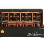
Ar9Jim 6,060 Posted October 16, 2023 Author Share Posted October 16, 2023 Here is a picture of one of the many awards at Bob's lab. 3 Link to comment Share on other sites More sharing options...


Recommended Posts