halfbaked 167 Posted October 17, 2023 Share Posted October 17, 2023 Thanks for a great tour. 1 Link to comment Share on other sites More sharing options...
Ar9Jim 6,065 Posted October 21, 2023 Author Share Posted October 21, 2023 (edited) It's a good day for a good day.. 285s start shipping next week. In on Monday out before Friday. This has a good chance of being the quietest tube amp available. It will be fun when they get out in the field. The guys with the 'measures best, so it sounds the best' mentality are already pigeon-holed to solid state only, but as far as tube amps go, this should set the standards for it's class. Both objectively and subjectively as Hugh Dean said when he simulated it as a consultant to confirm our simulations. Hugh confirmed the RAM 285 as good as we thought it was.. The reaction from Manufacturing Engineering was "Wow, Bob did this without simulation, using a calculator! Just about every tube amp starts to have some roll-off below 60Hz or so. This leads to the old assumption that tube amps are less desirable for bass frequencies. Not the 285. At full power frequency response is flat below 20Hz on a resistive load test at about .4% THD+N. Bob said he could take THD+N down to solid state levels, "but it would add complexity and have no sonic value." Most tube amp manufacturers spec FR at 1W.. The ASR test is at 5W.. Ram 285 is w/n minus 1-2 db at full power. The minus is at 20KHz It's a legacy product as intended Edited October 21, 2023 by Ar9Jim 2 1 1 Link to comment Share on other sites More sharing options...
xavionics 1,406 Posted October 21, 2023 Share Posted October 21, 2023 This is terrific news, Jim. Congratulations! 👍👍 There are soon to be some very happy (and lucky) recipients of Bob’s latest creations! 3 Link to comment Share on other sites More sharing options...
radtraveller 216 Posted October 21, 2023 Share Posted October 21, 2023 Woohoo… 🙂 Decisions…… Link to comment Share on other sites More sharing options...
Ar9Jim 6,065 Posted October 23, 2023 Author Share Posted October 23, 2023 (edited) Modern PCBs vs Point to point- Is point to point still better? With the point to point wired, 350 watt mono-block amplifier production coming to an end, the topic of point to point wiring vs modern printed circuit boards (PCBs) is a relevant topic to talk about. My background is in aerospace manufacturing and the state of the art processes used by the most highly regulated industry. It's through this lens that my view is filtered. The PCB was patented in 1956.. Having enjoyed restoring vintage tube amplifiers, its common to see PCBs from the 1960s that are burned and heat damaged. The thin, poor materials were poor at holding tube sockets. After the boards were exposed to heavy heat cycling from scorching hot tubes, the thin material could become carbonized and increased in conductivity, increasing noise from voltage creep between the often undersized traces. The thin boards would become brittle around the tube sockets. Changing tubes would often crack the well cooked boards and traces. If you have restored vintage tube amps, you have seen all of this for yourself. The materials were 1960's. Material science and engineering has not stood still for 60+ years any more than the design technology and materials used in automobiles from 1960 to 2023. You will still find some that would proclaim the 1960 autos better than today, but they are few. The saying, 'the best excuse for the good old days is a poor memory' comes to mind. The truth is, the old timers were right and the old PCBs in tube gear was a bad idea for longevity and audio performance. Point to point was the only way to go for an heirloom product to be passed down within generations of a family. Service life, noise level, measurable performance, hands down, point to point was worth the investment. It's 2023, these are not your fathers or grandfathers PCBs.. When do old facts become myths? Today our boards use heavy copper traces. The boards are multi-layer to allow for copper layers in-between, to be used as ground planes to isolate parts from each other when located on opposite sides of the board. This technology is a big step forward in noise reduction. We have now achieved lower noise levels with hi end PCBs than using point to point wiring. The high temp materials of today, combined with Bob Carvers cool running designs have made heat damaged and carbonized boards an issue in the past. The heat ratings of the modern materials could only be dreamed of in the 1960s. Today, the multilayer modern board materials and thru-hole plating of the tube socket locations, combined with proper mechanical mounting of the board to the chassis, has made board flex an issue in the past. Voltage creep between PCB traces is no longer an issue. The computer aided design knows the voltage in the traces and prevents spacing that would allow voltage creep to happen. Computer simulation is a tool only dreamed of in the 1960. Leveraging technology and science to provide a high end audio performance, at prices more people can afford has always been a worthy goal for Bob Carver. Today is no different. Delivering the highest customer value and sharing Bob's work with as many people as we can is the goal. Leveraging state of the art manufacturing technology, quality control and efficiencies for maximum performance and maximum value added for the customer is the path we are on. As always, Bob is all about pushing the cutting edge and improving performance. Combining the highest tech available with vacuum tubes is the way to truly advance tube amp performance. Edited October 23, 2023 by Ar9Jim 6 Link to comment Share on other sites More sharing options...
3M_Audio 883 Posted October 23, 2023 Share Posted October 23, 2023 8 hours ago, Ar9Jim said: Modern PCBs vs Point to point- Is point to point still better? With the point to point wired, 350 watt mono-block amplifier production coming to an end, the topic of point to point wiring vs modern printed circuit boards (PCBs) is a relevant topic to talk about. My background is in aerospace manufacturing and the state of the art processes used by the most highly regulated industry. It's through this lens that my view is filtered. The PCB was patented in 1956.. Having enjoyed restoring vintage tube amplifiers, its common to see PCBs from the 1960s that are burned and heat damaged. The thin, poor materials were poor at holding tube sockets. After the boards were exposed to heavy heat cycling from scorching hot tubes, the thin material could become carbonized and increased in conductivity, increasing noise from voltage creep between the often undersized traces. The thin boards would become brittle around the tube sockets. Changing tubes would often crack the well cooked boards and traces. If you have restored vintage tube amps, you have seen all of this for yourself. The materials were 1960's. Material science and engineering has not stood still for 60+ years any more than the design technology and materials used in automobiles from 1960 to 2023. You will still find some that would proclaim the 1960 autos better than today, but they are few. The saying, 'the best excuse for the good old days is a poor memory' comes to mind. The truth is, the old timers were right and the old PCBs in tube gear was a bad idea for longevity and audio performance. Point to point was the only way to go for an heirloom product to be passed down within generations of a family. Service life, noise level, measurable performance, hands down, point to point was worth the investment. It's 2023, these are not your fathers or grandfathers PCBs.. When do old facts become myths? Today our boards use heavy copper traces. The boards are multi-layer to allow for copper layers in-between, to be used as ground planes to isolate parts from each other when located on opposite sides of the board. This technology is a big step forward in noise reduction. We have now achieved lower noise levels with hi end PCBs than using point to point wiring. The high temp materials of today, combined with Bob Carvers cool running designs have made heat damaged and carbonized boards an issue in the past. The heat ratings of the modern materials could only be dreamed of in the 1960s. Today, the multilayer modern board materials and thru-hole plating of the tube socket locations, combined with proper mechanical mounting of the board to the chassis, has made board flex an issue in the past. Voltage creep between PCB traces is no longer an issue. The computer aided design knows the voltage in the traces and prevents spacing that would allow voltage creep to happen. Computer simulation is a tool only dreamed of in the 1960. Leveraging technology and science to provide a high end audio performance, at prices more people can afford has always been a worthy goal for Bob Carver. Today is no different. Delivering the highest customer value and sharing Bob's work with as many people as we can is the goal. Leveraging state of the art manufacturing technology, quality control and efficiencies for maximum performance and maximum value added for the customer is the path we are on. As always, Bob is all about pushing the cutting edge and improving performance. Combining the highest tech available with vacuum tubes is the way to truly advance tube amp performance. Good history lesson - thanks. I don't have any fond memories of nasty old fiberglass PCBs 2 Link to comment Share on other sites More sharing options...
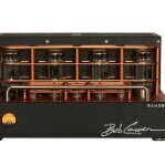
Ar9Jim 6,065 Posted October 26, 2023 Author Share Posted October 26, 2023 (edited) Today is a great day. RAM 285s are arriving and looking great. Initial test are great. The 285 is an overachiever subjectively or objectively running transducers or resisters. Here is the standard 1KHz power test driving 8 ohm resistors. The 85 watt amp made 125 watts at .3% distortion. This test was using a calibrated HP8903B using some free software available on-line. The Audio Precision analyzers have greater resolution than the HP8903s, but our quality manual requires that the test instruments have a resolution 10x greater than the tolerance allowed. The HP8903 meets this requirement well. At this moment the capital expenditure to replace the HP8903 isn't justifiable. Those who have experience tube amps know 125 watts is a lot of power, especially with no roll-off until below 20Hz. Pictures tend to make these look an odd color, but they are almost a perfect match for freshly stripped copper wire. Note one picture has a piece of copper wire placed on the chassis for reference. Edited October 26, 2023 by Ar9Jim 2 2 1 Link to comment Share on other sites More sharing options...
3M_Audio 883 Posted October 26, 2023 Share Posted October 26, 2023 Looks like a metalic paint? Sort of a lava color - always wanted a car in that color, lol I like the color contrast with the black pieces. 2 Link to comment Share on other sites More sharing options...
xavionics 1,406 Posted October 26, 2023 Share Posted October 26, 2023 Looking good Jim! 👍👍 Damn, the amp is entombed in foam - should survive even the most disconnected handler! Historic moments in the making this week…. 2 Link to comment Share on other sites More sharing options...
Ar9Jim 6,065 Posted October 26, 2023 Author Share Posted October 26, 2023 2 hours ago, 3M_Audio said: Looks like a metalic paint? Sort of a lava color - always wanted a car in that color, lol I like the color contrast with the black pieces. It's actually a bead blasted finish with copper anodize. 1 1 Link to comment Share on other sites More sharing options...
ChrisTFM35 598 Posted October 26, 2023 Share Posted October 26, 2023 Jim, if you need me to test this amp, I can do it. Send it my way for a free evaluation! 2 4 Link to comment Share on other sites More sharing options...
Kurt 1,393 Posted October 26, 2023 Share Posted October 26, 2023 Absolutely gorgeous piece of equipment. If they sound anywhere as good as they look, they will be instant classics in the market. I remember when the first iPad came out... I had this urge to just hold one in my hands. I have that same urge to just touch one of these beautiful amps. 2 Link to comment Share on other sites More sharing options...
radtraveller 216 Posted October 26, 2023 Share Posted October 26, 2023 The 85 watt amp made 125 watts at .3% distortion... Wonder how far I could push those without blowing a fuse on maggie 1.7.. soft clipping, higher voltages.. trade off to measured distortion, but at what point does that become audible? Wonder what wattage could be pushed if willing to accept a little audible distortion.. what is the absolute output wattage? The solid state a760x clips hard so probably blowing fuses due to that.. Speaking of clipping… If an amp creates high frequency artefacts at clipping which heats up and “blows” the tweeter, would adding a low pass > 22khz filter to the mid/highs amp (bi amped) can that mitigate tweeter damage when amp clips? 1 1 Link to comment Share on other sites More sharing options...
Ar9Jim 6,065 Posted October 27, 2023 Author Share Posted October 27, 2023 14 hours ago, radtraveller said: The 85 watt amp made 125 watts at .3% distortion... Wonder how far I could push those without blowing a fuse on maggie 1.7.. soft clipping, higher voltages.. trade off to measured distortion, but at what point does that become audible? Wonder what wattage could be pushed if willing to accept a little audible distortion.. what is the absolute output wattage? The solid state a760x clips hard so probably blowing fuses due to that.. Speaking of clipping… If an amp creates high frequency artefacts at clipping which heats up and “blows” the tweeter, would adding a low pass > 22khz filter to the mid/highs amp (bi amped) can that mitigate tweeter damage when amp clips? At 180 watts THD+N was at 7% when the test ended at more than double the rated output. It seems to be sort of accepted that 3% may audible. The overheating of tweeters from hard clipping of solid state is due to the tops on the nice smooth waveform being clipped off flat. To the driver, instead of having a wave flow when changing directions, it becomes more violent and abrupt. The heat goes up and bad things happen. With tube amps, the THD+N goes up, the wave form tops get distorted, looking thick and fuzzy at the peaks on a scope, but is easier on tweeters. I've only used the 285 on LRS+ and MGIIIA maggies. Xavionics was at the factory and we kept reaching over and turning it up a little more. The maggies were punching like dynamic bass drivers and the thought of film punching like that, made us stop out of fear for the maggies health. No blow fuses and no audible distortion.. Honestly, we looked at each other with amazement and Xavionics says "85 WPC, yeah right!" Bob hit a homerun. A true legacy product. 2 1 Link to comment Share on other sites More sharing options...
wrf 3,829 Posted October 27, 2023 Share Posted October 27, 2023 1 hour ago, Ar9Jim said: At 180 watts THD+N was at 7% when the test ended at more than double the rated output. It seems to be sort of accepted that 3% may audible. Wow. One or two channels driven? 1 Link to comment Share on other sites More sharing options...
Ar9Jim 6,065 Posted October 27, 2023 Author Share Posted October 27, 2023 26 minutes ago, wrf said: Wow. One or two channels driven? Just 1 this time. I'll try 2 next and we can compare. The power trans should good for about 350w.. At 1K the output trannies should be fine. I'll post FR at a 5 volt output spec and at rated power, also.. Flat line past 18hz with no roll-off at 20Hz.. Bad ass tube amp.. Fun stuff! Today the bias resistor values are being adjusted to allow the bias pot slightly more range of adjustment to the higher side. 1 Link to comment Share on other sites More sharing options...
Ar9Jim 6,065 Posted October 27, 2023 Author Share Posted October 27, 2023 (edited) Hi Wayne, Here is a test of both channels driven 4 ohms this time. With both channels driven it made 125w at .46% THD+N and when the test stop it was 157w @7%. There is a frequency plot shown both channels driven. There is a .25 db dip by design. This is at 5 watts as tested by many. The FR is the same at full power. My low buck 10a variac on the shelf (red). Bob's on the shelf is a 22a big guy. Note this is not +- 3 db. This is plus only 1.1 db at @25 KHz. Edited October 27, 2023 by Ar9Jim 3 1 Link to comment Share on other sites More sharing options...
xavionics 1,406 Posted October 27, 2023 Share Posted October 27, 2023 A lot of excitement surrounding the release of Bob’s latest creation. And with good reason! It needs to be stated, though, that the prototype has had the shit kicked out of it since it’s debut at AXPONA last April. We ran the snot out of it for 3 days, after arriving still warm from Bob’s testing. Its been Jim’s daily driver at The Factory ever since (I believe). We ran the snot out of again a few weeks ago at The Factory, doing some experimentations with different sources and a few different speaker configurations. Damn, those Maggie’s danced beautifully with such a strong partner! All without so much as a whimper! When my disposable income account recovers, the RAM285 is on my short list of things to acquire… ….sadly that may take a while though…… 3 Link to comment Share on other sites More sharing options...
4krow 5,077 Posted October 27, 2023 Share Posted October 27, 2023 Jim, I agree with so much of what you are saying about circuit boards in this thread. The 'but' is that even today there are those out there that use really crappy boards no matter how well designed, and it just seems that more people would jump on board with better quality boards. As far as I know Glassware Audio has made the finest boards that I have ever worked with. They ARE thick, the traces heavy and even look cool. Here is my issue>> if everything is place in the right orientation, and the right values are used, you are done and it will last a lifetime. OTOH if you have to remove a part for any reason, I can't ever seem to do it successfully. This is because of two things. Mostly it is the through hole plating that can come off right with the lead being removed! Secondly, the new designs have holes so small that apparently it makes removing solder much more difficult. And well hell let me bring another problem while I am at it. The fraking solder used from some factories, is unbelievably crappy! You have to heat it to 900 degrees with a rosebud torch to get it to melt. Now assuming that all of these troubles are taken care of before production begins, it is then that I completely agree with you. Point to point is really challenging at times, especially if you want it to look decent. The one thing that I do love about it is the ability to mechanically attach sockets right to the metal chassis. But when push comes to shove, a properly made board can do all of that. 3 Link to comment Share on other sites More sharing options...
Ar9Jim 6,065 Posted October 27, 2023 Author Share Posted October 27, 2023 (edited) Agree Greg. Point to point does have some upside. Our boards are custom made. The materials, copper weight, etc. are called out in the design. Computer design software really helps avoid issues ahead of time. Voltage creep, EMI and other issues are avoided. Here is an example of the vintage boards that were basically junk. This is where the circuit board 'truths' that are now myths originated. They were terrible. Check out the thin warped board. Note the burned area on the opposite side from the tube socket. Note how poorly it is mechanically attached. Imagine pulling and pushing tubes out of the socket attached to the thin crispy wafer of micarta? Will the traces survive? I'm not sure, but it appears there may be signs of voltage creep between traces, what do you think? Here is a multilayer thick high quality, state of the art heat resistant board. Heavy copper traces computer aided design. Gold plating to prevent oxidation. Vent holes for air flow. Note the mounting screw locations to support the board properly eliminating flex. Lower noise floor. Reduces the cost of the final product to the customer by a large margin. Edited October 27, 2023 by Ar9Jim 3 Link to comment Share on other sites More sharing options...
4krow 5,077 Posted October 27, 2023 Share Posted October 27, 2023 (edited) They don't make 'em like they used to (I am being faciscious). I am remembering those awkward little transistor radios along with everything else. I don't remember what the boards were like in the TV sets, but I do remember what the insides of my Marantz 1060 looked like. Not something to brag about, I will say that much. First time that I saw something beautiful inside of an amp it was made by Nakamichi. A Ca5 and PA5 set that I had. Blue circuit boards and heavy power supply rails? I mean copper rails. That was the late 80's (memory lapse). Edited October 27, 2023 by 4krow All fixed up translation 2 Link to comment Share on other sites More sharing options...
Ar9Jim 6,065 Posted October 27, 2023 Author Share Posted October 27, 2023 "They don't make 'em like they used to." Oh man, that's a good thing.. I don't miss drum brakes or bias ply tires either.😊 1 4 Link to comment Share on other sites More sharing options...
jeffs 2,605 Posted October 27, 2023 Share Posted October 27, 2023 (edited) 2 hours ago, 4krow said: The 'but' is that even today there are those out there that use really crappy boards no matter how well designed PC board quality has come a long way. You have to try really hard to get low quality boards these days. Even low-cost boards from the hi-end Chinese houses are very good. You can dial in everything - pay as you go. Copper weight, layer thickness, board material, etc. 20-25 years ago if you went low end - it was pretty bad. Not going to name names, but some of the Carver amps built in the first 1/2 of the 90s have very poor quality PC boards. Corners were cut in that timeframe. Edited October 27, 2023 by jeffs 3 Link to comment Share on other sites More sharing options...
4krow 5,077 Posted October 27, 2023 Share Posted October 27, 2023 I'll have to find some of those boards that I am referring to. Yes the board material is better than the absolute crap way in the past, but there is just something about a damned near see through thin board that I want nothing to do with. When I accidentally order such a product it never gets built. Don't want my name on it. Funny though, they still find their way into important appliances and other equipment where they don't belong. Not just audio. 4 Link to comment Share on other sites More sharing options...
Ar9Jim 6,065 Posted October 27, 2023 Author Share Posted October 27, 2023 (edited) 3 hours ago, jeffs said: PC board quality has come a long way. You have to try really hard to get low quality boards these days. Even low-cost boards from the hi-end Chinese houses are very good. You can dial in everything - pay as you go. Copper weight, layer thickness, board material, etc. 20-25 years ago if you went low end - it was pretty bad. Not going to name names, but some of the Carver amps built in the first 1/2 of the 90s have very poor quality PC boards. Corners were cut in that timeframe. Some of the boards with the lifting traces are a pita.. Too many times, I didn't lift off the trigger on a solder sucker before lifting it off the solder pad and lifted the pad off the board. Interesting to be old enough to see these improvements over time. 1960s like that Dynaco to 1990s while they were generally a lot better, but still not so good for tube amps, to 2023 when you can call out copper weight and the specs engineers want. Even DIY. Good times really. Edited October 27, 2023 by Ar9Jim 4 Link to comment Share on other sites More sharing options...


Recommended Posts