Leaderboard


Popular Content
Showing content with the highest reputation on 09/11/2023 in Posts
-
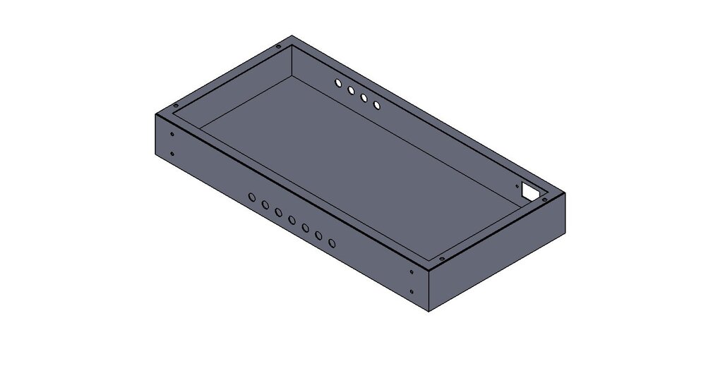
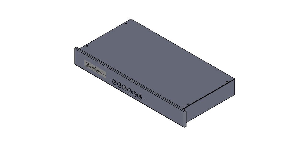
Now I'm designing a single work holding fixture for machining the chassis and the face plates. The X - Y pickup point for zeroing the machine will be machined into the fixture itself. I'll show pictures of the tooling. This tooling will allow the parts to be removed and replaced in the machine quickly while locating them properly. This is key to keeping the machine running and reducing cycle times. Reducing cycle times reduces cost and keeps the USA competitive. I'll show you CAD, then show pictures of tooling in real life, then prototypes on manual mill and then production on a CNC, metal finishing, laser, silkscreen. assembly etc.. Hope its fun to see what it takes and how the process evolves.6 points
-
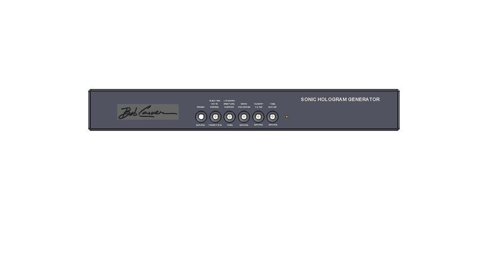
Hey Chris, Ok here are the concepts. The Bob Carver signature will be in white like the rest of the script. The chassis is deep enough (8) inches to allow stacking. Its also deep enough to accommodate the tube buffer option with tubes sticking through the lid with copper cages similar to the Ram 285.. We are thinking about using the same hole pattern on the chassis, regardless if the buffer option is selected or not.. This way the buffer could be added at a later date if desired, with minimal modification. Those without the buffer will still have the switch installed. Faceplate will be radiused to match V12 and 285 . The button recesses and buttons match the V12 buttons. Some items from your request. 1) Power button on the face. 2) Gundry filter (switchable). 3) Can be purchased with a switchable tube buffer showing glowing exposed tubes. 4) Can be purchased without a tube buffer with a flat top surface suitable for stacking. 5) Make it deep enough to be stackable. Radiused to match the Ram 285. Smooth and modern. This is old CAD software but plenty capable for this type work.
 6 points
 -
I would like to see the new C9 have a remote to switch SH on/off, and maybe some of the "options- Grundy filter, Wide/Narrow, etc" switchable as well. Not having a remote would probably be a deal breaker for me because you want to be able to hear the effect in/out from your listening position. It should have both balanced and unbalanced inputs/outputs as well. No need for tubes IMHO.5 points
-
Measured my space that I have available. 19 inches wide, 17 inches deep, and 8.5 inches high. Placed a " Coming Soon - THIS Space set aside for your listening enjoyment" sign on that space. Thanks for concept drawings and word visuals.5 points
-
Sure. We talk almost every day. I gather and propose ideas, but Bob's has his own ideas and final approval throughout the process.4 points
-
I'm ready to see pictures of the concept.4 points
-
Jim...I will summarize all of this great new info and post it in the Facebook SH page. Thanks for the information.3 points
-
The idea of a new Carver processor box would be an idea I would go for. Also having the tube optional is another good idea. Some of us don’t have the room or the right amount of cool to the room without turning on the A/C.😁2 points
-
I'd be in.. especially around that price point! Personally, meters would be a nice aesthetic touch. Exposed tubes I could take or leave depending on the final design.. not a deal breaker either way. There's a lot of good suggestions here, but of course a price to feature balance needs to be struck. Looking forward to seeing the final product!2 points
-
Ar9Jim: If Bob has interest in full cancellation SH, have him send me a PM. I'll dig my schematic out of storage. I have one of my C4000s working with the mods.1 point
-
This is great news!1 point
-
There should also be a rotary knob, unlabeled. It may or may not make a difference. Sheez, once something good gets to be too complicated, then it becomes a rat chasing its own tail. Hit and miss. One appealing aspect of the original was its price.1 point
-
I have noticed that Tidal has stopped promoting the MQA designation.1 point
-
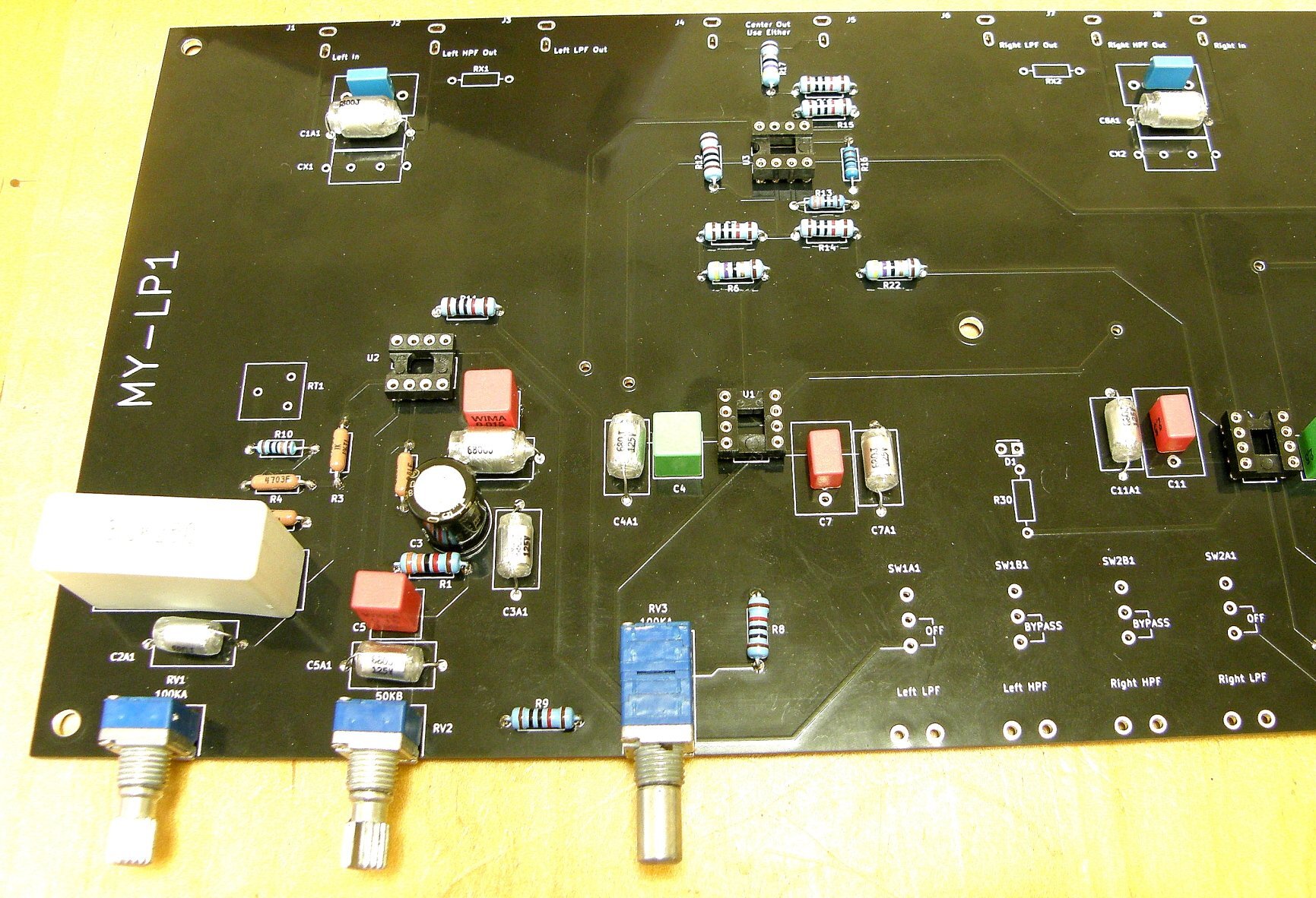
I recently posted on a thread from @Dadvw regarding a blown plate amp and I mentioned a project @jeffsand I were working on for an active crossover that, while it is based on a Dahlquist DQ-LP1 design, incorporated a modern power supply, modern multi layer board with a ground plane, newer components, and a revised circuitry. Some background, I've been using the Dahlquist DQ-LP1 for years. There is a lot of info on the internet if you want to grab a copy of the manual and schematic. Like the C-1, it has a loyal following including hobbists that have documented numerous improvments over the years. I've collected a lot of info and can post it if desired. I drive 2 subs, a left channel and a right channel. Common practice is to use a mono sub as "low frequency is non-directional". I was watching a Paul McGowen video on multi subs and he addressed that the frequency of a sub goes from non-directional to directional - he strongly advocated dual subs. I researched the internet and you can't get a straight story, one of the prevalent therories is that LF sound is non-directionsl under 400hz since that is equivilent to the spacing between the average human ears. Sounds hokey to me. Here's what I know, I can run a low frequency signal and I can point directly to the sub. Maybe I'm just weird and have a thin head. IMHO, for 2 channel music, if you feel you need a sub then you want ideally 2 subs. One by the Left speaker and the other by the Right, each being fed by their respective independent stereo channel. Picture to follow of my layout (room size and layout is not perfect but you work with what you have). You'll see a set of Dahlquist DQ-SW1 subs, with JBL L100t perched on top of them. I use the preamp signal (4000t), and feed it into the Dahlquist DQ-LP1. The low pass signal (independent L and R) feeds a TFM-24, which feeds the SW1s. The HP goes into a TFM-42 and feeds the JBLs. The DQ-LP1 is an old unit. @jeffs and I (mostly Jeff) redesigned the DQ-LP1 (MY-LP1) to improve it. This was not and is not intended as a commercial project, just an interesting personel project. I can post more on the project if interested.1 point
-
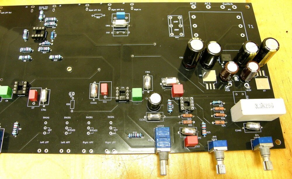
Only one more switch to install. Next, chassis decision.

 1 point
 -
That brings another topic to the thread that is not very well understood in the audiophile realm. Would you believe that the impedance dips were allowed remain in the Kappa 9s because they were intended for tube amplifiers. The Kappa 9s can be ran on fairly small tube amps. At the time, the Kappa nine was recommended for use with "vintage" (tube) amplifiers. "Nice wide voltage swing and lots of headroom" B. Carver, is the answer. Actually a Black Magic 25 would power Kappa9s way better that many people could even comprehend. A search for Kappa 9 / tube amp has a lot of info.. People running smaller tube amps after burning up solid state. Not intuitive but true non the less. Paul talks about tubes and Kappa 9s in the video. This is also not intuitive to the common audiophile beliefs in solid state, about an amplifier needing to double its output from 8 to 4 ohms in order to run difficult loads. Tube amps don't double as the impedance is reduced by half. Usually 8 and 4 ohm output is not much different. Bobs DC restorer makes them even better.1 point
-
I thought Ethan Winer addressed the wire issue nicely with this YouTube post:1 point
-
Allman Brothers I'm No Angel1 point
-
John S., About the 160-degree presentation of the C-9, yes, you are correct about that. In fact, it is one of those things that make me turn my head occasionally. The other device that I had heard in the past somehow went a bit beyond this and was too much of a good thing. It was rather impressive in its presentation, but not believable. Our brains will only accept so much as they will and filter out all the rest as BS. Maybe that is how I think of many things in life. We normally are hit daily with so much BS. Then again, just look at the number of sunsets that just don't 'look right'. I concur with your statement about improvements coming in the new C-9 design. You can bet that Bob is likely to be doing something in that sense. I still am pushing my idea of having a variable type of SH (like a volume control knob for SH) rather than 2-3 presets. Each recording probably has a 'best' amount of SH.1 point
-
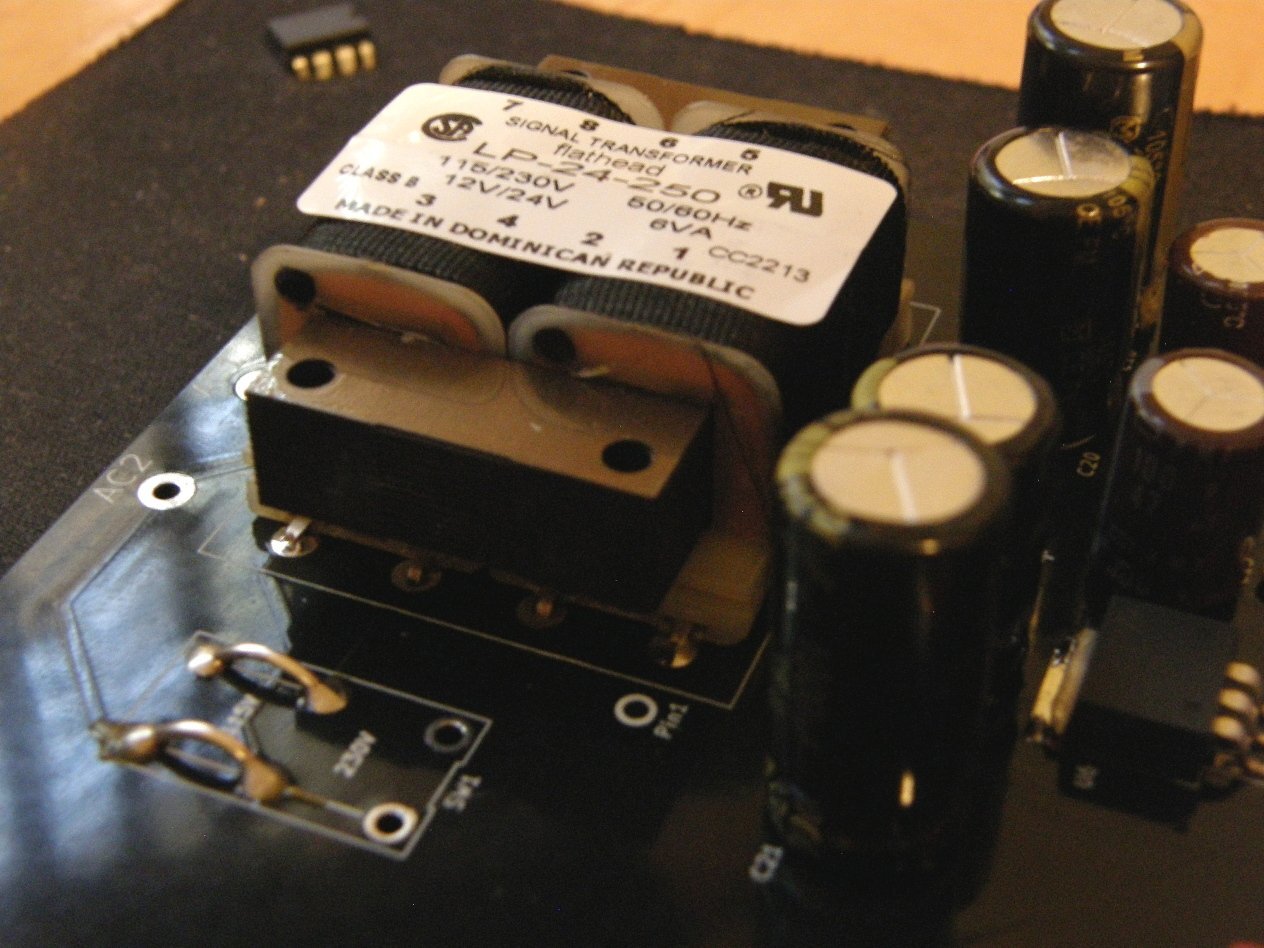
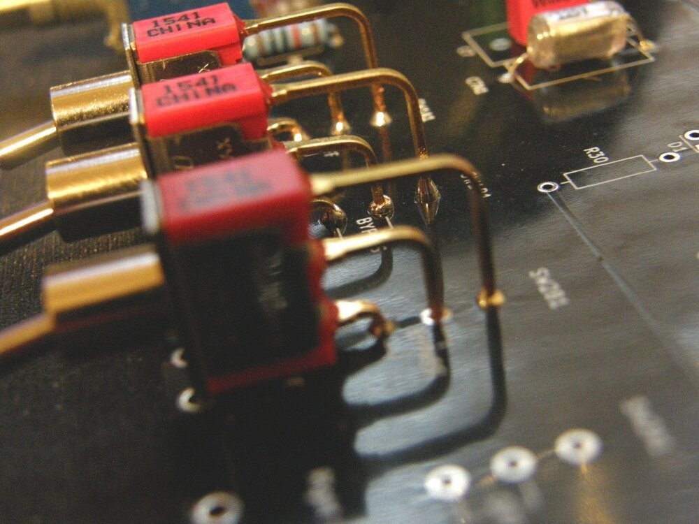
Sorry, not great photos but this gives a bit of an idea of where I am at so far. Fingers crossed, I may have a suitable transformer downstairs. Crap, I just checked, and the tranny isn't the one needed for this project. Jeffs, Note the 3.3uf output capacitors instead of 2.2 It is what I had and figured that it would not be a problem, but am checking with you just to be sure.
 1 point
 -
Yes sir that's exactly how it works. If for instance you plug in the 100hz card it sends 100hz and up to the high side and 100hz and below to the subs. Vacuum tube amps crossover at a different point than solid state amps. Something to do with their speaker output taps. A vacuum Tube amp is around 100k ohms and SS is around 10k to 33k ohms. This changes the crossover point. Example: one of my cards crosses over at 78hz with a Vacuum tube amp and the same card crosses over at 350hz with a solid state amp. So Mark made me several cards to cover vac vs ss.1 point
-
I am sorry Jim if I referenced you in this post. I meant to ask Jvandke if he has discussed his SH mods with Bob persoanlly since he suggests that updated changes need to be made for the newer vrsion you are working on.0 points